

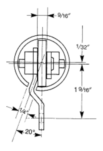
Straight power track is 1-5/8" O.D. x 1-3/8" I.D. open seam steel tubing with a 1/4" slot. The track is installed with the slot 20° off the vertical centerline.
Straight track is fabricated from special cold formed steel and is available in 20 ft. lengths.
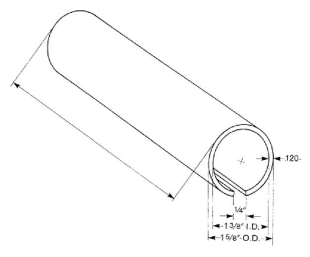
Power curves are fabricated from 1-5/8" O.D. x 1-3/8" I.D. steel tubing and heat treated to withstand normal wear.

To determine the slot position, start at the drive as shown on the diagram below.
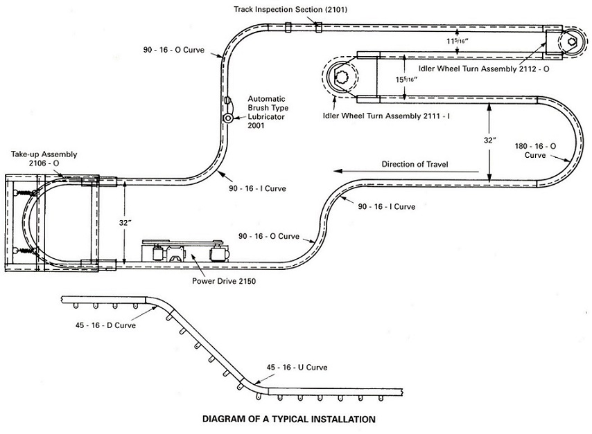
The drive rectangle drawn and installed on the inside of the loop indicates that the slot in the take-up immedediately following is an outside slot. If the drive were drawn and installed on the outside of the loop, the take-up would be an inside slot take-up. The vertical drive has no slot location due to the fact it can be turned end for end.
The first 90° curve following the take-up is an inside slot. The second 90° curve is an outside slot; if this curve made a left hand turn (back towards the take-up) it would be an inside slot.
Vertical curves do not have an outside or inside designation as they can be turned end for end, thereby changing the slot position. They are only referred to as "U" for UP and "D" for DOWN.
Up curves exist at the bottom of an elevation change. Down curves always occur at the top of an elevation change.
Always remember that any elevation change requires two (2) curves; one (1) up and one (1) down.
NOTE: Butted joints should be avoided between vertical and horizontal curves. Always insert at least a 12" section of straight track between such curves.
Part No. |
Description |
2100 |
Straight Power Track (20 ft.) |
PURCHASING DESCRIPTION:
General form: Part No./Description
(Example: Part No. 2100 - Power Track)
Copyright © 1stSource Products, Inc. All Rights Reserved